
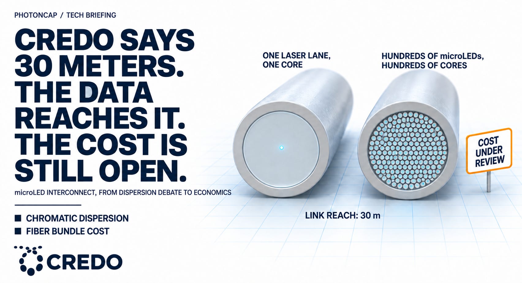
On the September 1 Credo earnings call, CEO Bill Brennan put the reach of the company’s microLED cable at 30 m and called it “just step 1.” For the past year there has been a well-traveled objection to this technology: LEDs have a broad spectrum and spray light in every direction, so they cannot work in a data center. I put the documents behind that objection next to the measured paper on the other side, and next to the Hyperlume patent published on September 3, and read them together. The physics the objection points at is real. But how far that physics has already been worked around is a matter of published numbers, and the numbers are ahead of the objection. While digging, one thing caught me. The biggest question is moving from whether it works to whether it works at production cost, and that cost is set by the fiber bundle and the equalizer. My read is that who holds those cost items decides the order in which the tickers get exposure.
Contents
The September 1 Call and 30 Meters
The 10 to 30 m Skeptics’ Case
How Far MOSAIC Actually Sent Data
The Hyperlume Patent and the Fiber Variable
Fig. 4f in the SK hynix Paper
What Decides the Economics
Exposure by Ticker
Closing
1. The September 1 Call and 30 Meters
When I wrote in early July that five listed companies had crowded into microLED interconnect, $CRDO was near $257. The September 14 close is near $150, with a market cap in the $28 billion range [1]. It lost more than 40% in a little over two months, and over the same stretch the microLED news actually got better. That gap is why this piece exists.
On the September 1 call for the first quarter of fiscal 2027, Brennan put this into his prepared remarks. ALCs (Active LED Cables, active optical cables that use microLEDs instead of lasers as the light source) use micro emitters to carry the reliability and power advantages of copper out to 30 m, the company will demonstrate them at OCP in October, and first revenue stays in fiscal 2028 [2]. In the Q&A he went one step further.
“Key difference there is we will extend the length to 30 meters.” ... “I think that is just step 1 for ALCs and the micro emitter technology. A next natural step forward on that is to apply that to what comes with the scale up opportunity.” [2]
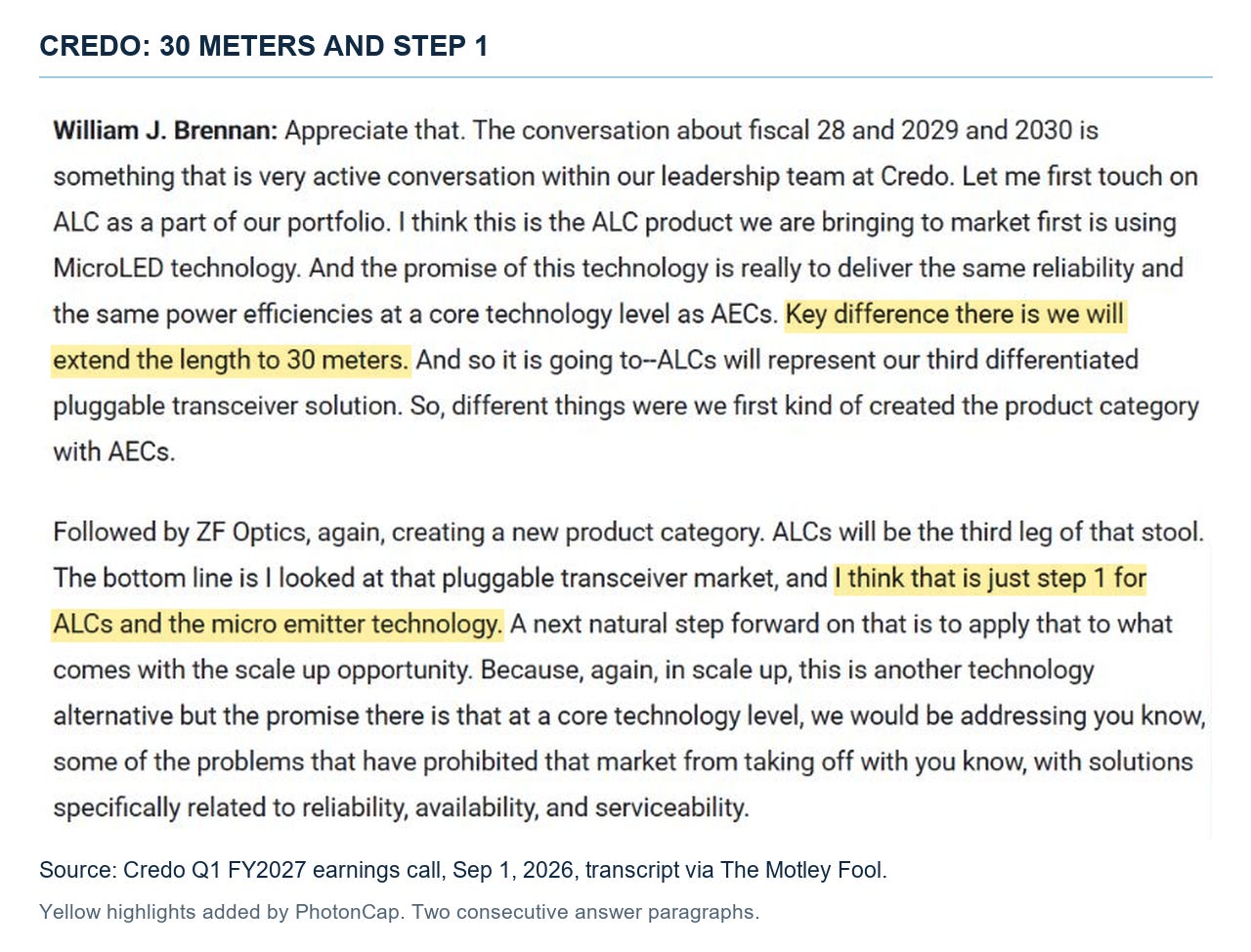
The 30 meters and step 1 passage from the Credo Q1 FY2027 call transcript
Revenue for the same quarter was $479 million, more than double a year earlier [3], and the full-year target of more than $600 million in optical revenue stood as before on the call [2]. So the first thing to check off is that the company pulling back its ALC schedule was at least not the cause of this drawdown.
He said the same thing at the Goldman Sachs conference on September 10. The company has been looking at micro emitters for three years, the promise is to take the 7 m of an AEC (Active Electrical Cable, a copper cable with a signal-restoring chip inside) out to 30 m while keeping the same reliability and power efficiency, and the cable is 75% smaller by volume than a 7 m AEC at 200G per lane [4].
So why does the number 30 m matter? Today the scale-up wiring (the links that bind GPUs together as one machine) ends in copper inside the rack. Going beyond the rack to a row takes 10 to 30 m, and until now that range has belonged to laser optics. Credo’s product page targets exactly this range [5]. And 30 m is exactly the distance the skeptics have said dispersion blocks.
2. The 10 to 30 m Skeptics’ Case
The original form of the objection is a 2022 IEEE Spectrum article. LED light is incoherent, so dispersion restricts it to about 10 m, one line [6]. That line still gets quoted a lot. In March this year Network World covered the Microsoft result and quoted Neil Shah of Counterpoint, who granted the power advantage but argued that chromatic dispersion limits reach, that dedicated cabling and rack changes cost money, and that adoption is hard without NVIDIA and AMD [7]. A December IEEE Computer Society piece is more technical. microLEDs have a wide divergence angle that makes fiber coupling hard, dense multicore fiber brings crosstalk between channels, and dispersion is only acceptable under 30 m [8].
Some terms need sorting here or the rest gets confusing. People lump this together as “interference between colors,” but three different things are going on. Chromatic dispersion is light of different wavelengths traveling through glass at different speeds, so a pulse with a broad spectrum spreads out front to back the farther it goes. Modal dispersion is light inside a thick-core fiber splitting into several paths and arriving at different times. Spatial crosstalk is light from a neighboring channel leaking into yours. Today’s wide-and-slow microLED designs, MOSAIC and Avicena’s LightBundle, do not stack colors onto one fiber the way WDM (wavelength division multiplexing, one fiber carrying separate channels by color) does. They send hundreds of emitters down separate cores in parallel, so colors colliding with each other was never the problem. The problem is chromatic dispersion from the fact that one microLED’s emission spectrum is far wider than a laser’s, not interference between WDM channels.
How much wider? By the Microsoft paper’s numbers, a laser linewidth is under 1 pm and a microLED’s is over 10 nm [9]. A full ten thousand times. Anyone can calculate how much that hurts. The material dispersion of fused silica at 450 nm is about -770 ps/(nm·km) (my own calculation from Malitson’s 1965 refractive index equation [10]). Assume a 25 nm spectral width and send it 50 m, and the pulse spreads by about 960 ps. At 2 Gbps one bit is 500 ps, so the smear is about two bits long. Cut the distance to 20 m and it is about 385 ps, inside one bit. One more thing to note here. Data center lasers sit in the near infrared at 850 nm or 1,310 nm, and the same calculation gives silica dispersion of -84 at 850 nm and close to zero at 1,310 nm [10], so a laser has a narrow linewidth and also sits at a wavelength where dispersion is practically absent. A microLED has to send a broad spectrum in the blue that GaN emits, which is the wavelength band where silica dispersion is largest, so the handicap is doubled. This one piece of arithmetic explains why this camp keeps lane speed around 2 Gbps and why the line falls somewhere between 20 m and 30 m (author calculation, a first-order estimate of material dispersion only, for silica, so actual fiber materials will differ).
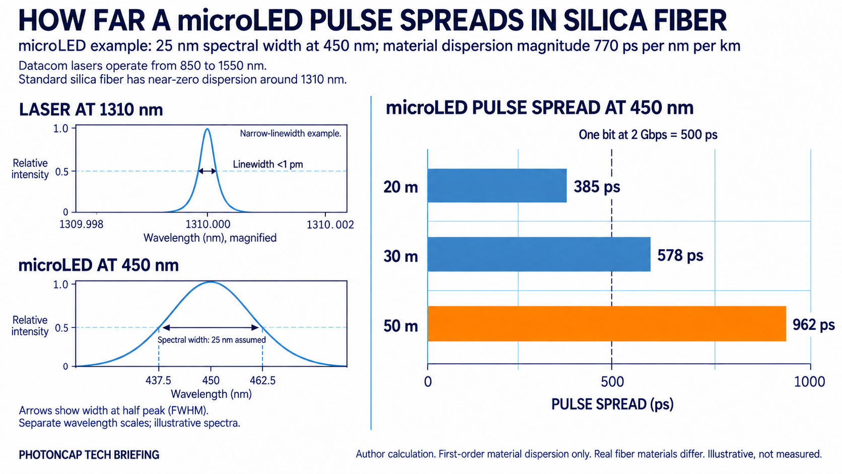
Laser at 1 pm vs microLED at 25 nm, how far the pulse spreads at 20 m and 50 m
The orange bar in the figure is the spread at 50 m, and you can compare it with the bit period box next to it. So the physics the objection points at is correct. Reading the skeptics, I could not find a sentence that was wrong. But the conclusion the skeptics usually reach is “so 30 m is out of reach,” and for that conclusion to hold there would have to be no lever at all for reducing dispersion. If there are levers, the story changes. How the three light sources split by distance is covered in The AI Light Source War Is Not a Speed Race: InP, VCSEL, and μLED Are Buying Different Distances, so here I look only at the levers.
3. How Far MOSAIC Actually Sent Data
The evidence that levers exist sits inside the very paper the skeptics cite. MOSAIC, which Microsoft Research presented at SIGCOMM in September 2025 [9]. With a 100-channel prototype it sent 2 Gbps per channel over 20 m, and at 30 m it had to drop to 1.6 Gbps. To be precise, the bit error rate at 20 m was under 10 to the minus 6, more than 100 times below the error correction threshold used by Ethernet and InfiniBand. At 30 m, 2 Gbps edged just over that threshold, so they dropped to 1.6 Gbps [9]. A simulation assuming production-grade parts gives 2 Gbps at 50 m, and more than 8 Gbps per channel within 10 m [9].
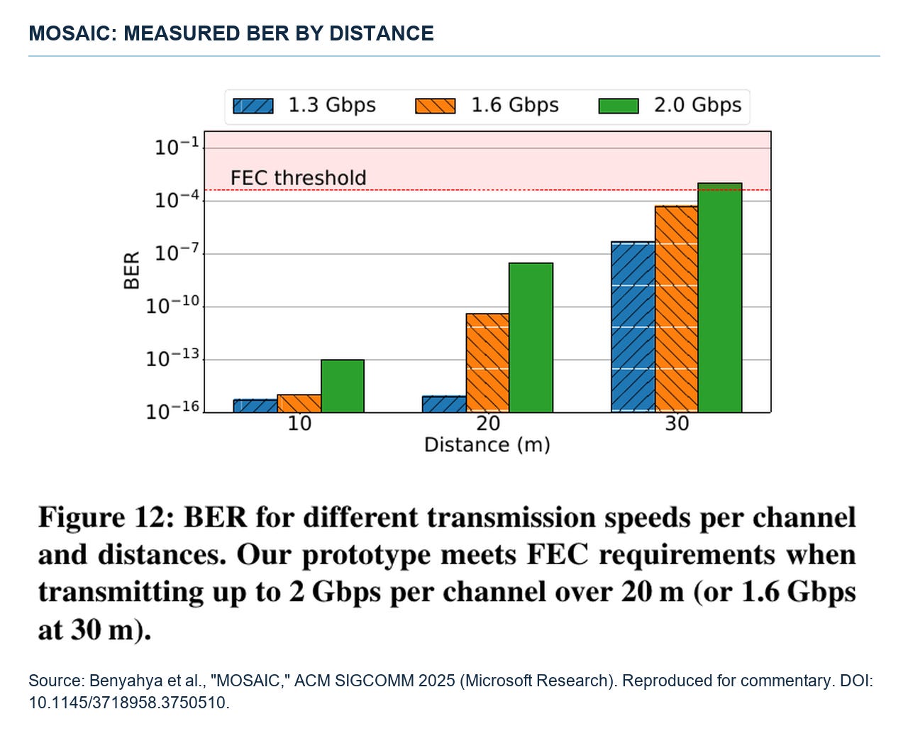
MOSAIC paper Fig. 12, measured bit error rate by distance
There is one thing to be careful about when reading those numbers. The paper notes that hand-wiring 100 drivers was complicated, so each experiment ran 25 channels at a time [9]. It was not a measurement of 100 channels driven simultaneously. Still, they said any 25 channels could be chosen, so each channel on its own was validated.
How did they get past 20 m? One lever is the direction of the light. Without a lens a microLED emits into the whole upper hemisphere, ±90 degrees, but after printing a micro lens built on total internal reflection (TIR), the beam collimated into a ±12 degree cone, fiber coupling efficiency went up, and crosstalk between channels went down, according to the paper [9]. The paper’s claim is that these lenses can be mass-produced at wafer scale by nano-imprinting. The next lever is the fiber. They used imaging fiber, the kind used in endoscopes, with up to ten thousand cores in a single strand, and found it was actually better to spread one microLED across several cores [9]. The last is signal processing. Each channel runs NRZ with only two levels, 0 and 1, and because the speed is low the spread pulse is rebuilt with analog equalizers alone, with no DSP (the digital signal processing chip that eats a large share of today’s optical module power) and no ADC/DAC [9]. Error correction was not removed altogether. Instead of a separate high-speed FEC block inside the module, the design keeps the Ethernet PCS layer FEC as is, and adds a lightweight Hamming code plus spare channel switchover for channel failures [9]. Dispersion was not eliminated in the fiber. It was contained within a range that slow lanes and analog correction can handle.
What they got in return is power. The estimated power for one end of an 800G link, counting the host interface, the digital backend and the light source, is 3.1 to 5.3 W, more than half below the 9.8 to 12 W of today’s laser 800G optical links measured the same way, by the paper’s numbers [9]. The digital backend is only 0.4 W because there is no DSP and no ADC/DAC.
One more thing worth writing down here. 30 m is a number Credo did not produce first. Avicena announced at ECOC in September 2024 that it had extended LightBundle’s reach from 10 m to 30 m, and its CEO at the time said 100 m or more could be possible [11]. So Brennan’s 30 m is less a declaration that broke a physical limit than a listed company putting a distance a startup demonstrated two years ago into a product spec. 30 m has been shown separately in two places, and what remains is doing it in a production cable at a price.
4. The Hyperlume Patent and the Fiber Variable
As it happens, on September 3 the US Patent Office published one of Hyperlume’s applications. The title is “System for Optimizing Propagation and Dispersion of an Optical Signal” [12]. Hyperlume is the Ottawa microLED startup Credo acquired last September [13], and this application was filed in February 2025, seven months before the acquisition. Among the three inventors are Hyperlume’s CEO Mohsen Asad and CTO Hossein Fariborzi [12], so the front page also tells you this was a problem the founders worked on themselves.
The contents aim straight at the problem in the previous section. The background states that a microLED’s wide spectrum causes chromatic dispersion that cuts the effective bandwidth of a signal passing through fiber, and the solution works on the fiber, not the light source. It sets the core’s numerical aperture (NA, the range of angles a fiber accepts light from) between 0.17 and 0.7, the core diameter between 2 µm and 400 µm, suppresses modal dispersion with a GI (graded-index) structure in which the core’s refractive index falls off gradually from center to edge, and chooses the core material from fluorinated polymer, PMMA, or silica-based glass [12]. It comes with drawings. FIG. 7 plots the dispersion coefficient of the three materials on one graph from 400 nm to 1,600 nm, and FIG. 8 tabulates, for seven fiber samples with NA from 0.14 to 0.63, the bandwidth allowed by modal and chromatic dispersion at 1 m, 3 m and 10 m. At 10 m the chromatic dispersion bandwidth is 2.8 GHz for most samples and 5 GHz at best [12]. The line is drawn in the same place as the arithmetic in the previous section.
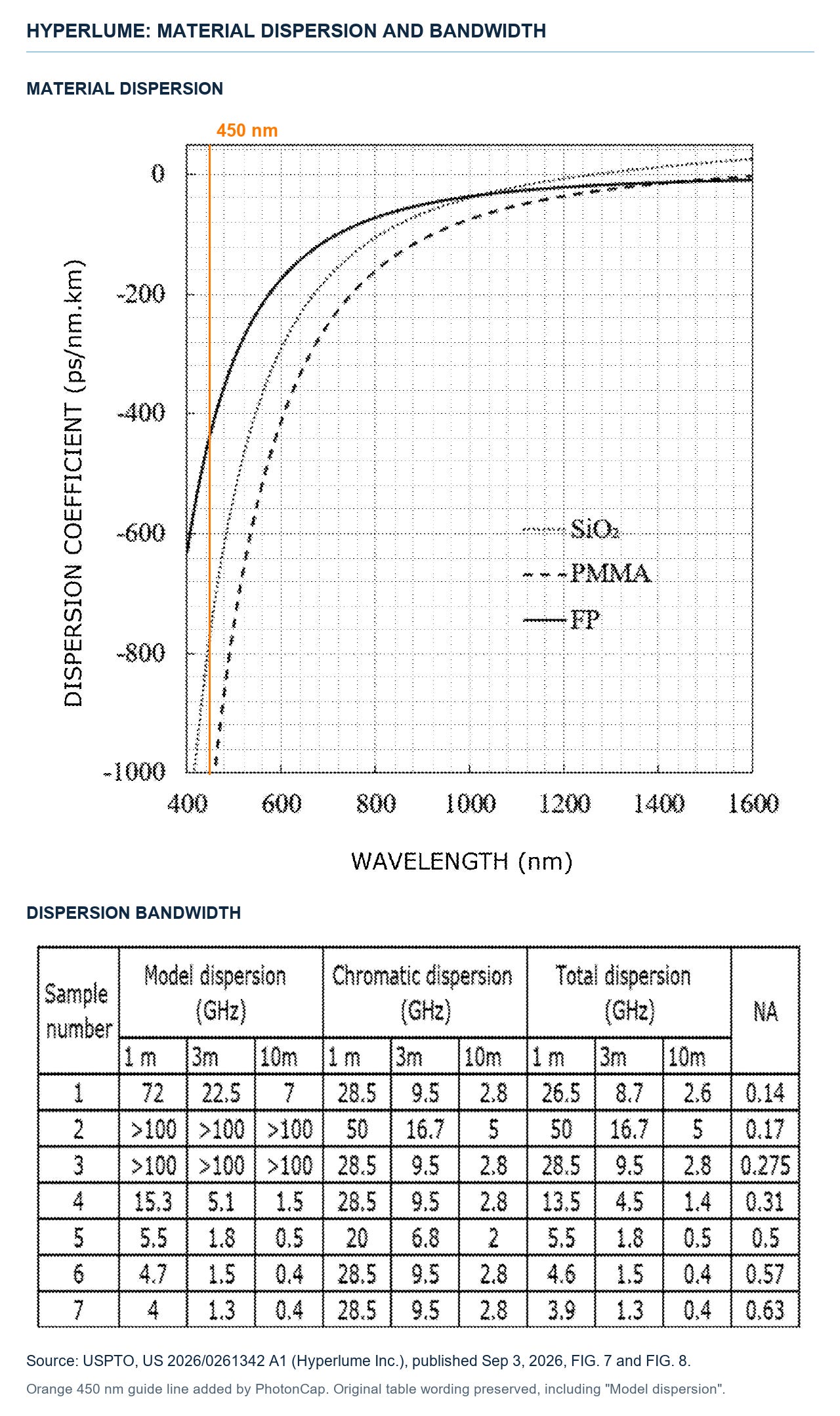
Hyperlume patent FIG. 7 dispersion curves and FIG. 8 dispersion bandwidth table
One line to draw in advance: 30 m appears nowhere in this patent. The existing microLED link distances in the background are 1 to 10 m, and the worked examples are 1 m, 3 m and 10 m [12]. So writing that this application is the technology that made the ALC’s 30 m would be an exaggeration. What I read into it goes this far: the team Credo bought had been building IP that handles dispersion through fiber design since before the acquisition.
How five listed companies came into this seat is laid out in The microLED Light Source Was Just Avicena. A Quarter Later, Five Listed Tickers Piled In. In that piece I wrote that microLED is an option inside platform names, and over two months the physics behind that option got thicker while the stock price fell.
So if the physics is solved, what fight is left? From here on we go past what public sources show. Why the material list in that patent caught my eye, where the money to cut dispersion in the fiber comes from, where the lane speed ceiling of a DSP-free equalizer sits, whose hands hold the cost of plugging hundreds of strands into a connector, and when those items reach each ticker’s P&L, that is the paid section. Before that, one picture from the memory side.
