
$1.1M Revenue, $1.1B Market Cap: The “Assembly Stage” POET Is Actually Holding
Three pieces of equipment in a video, six peer-reviewed papers, and the Marvell-Celestial-POET-Sivers supply chain

POET generates $1.1M in TTM revenue. Its market cap sits at $1.1B (as of April 17, 2026). PSR of roughly 1000x. What the market is pricing is not revenue. It’s the “stage” POET is holding. This article starts with the actual equipment POET showed in its 12-month review video (June 2025), works through six peer-reviewed papers, and traces the four-company supply chain (Marvell-Celestial-POET-Sivers) that formed between Celestial AI’s April 2023 advanced purchase order and Marvell’s Celestial acquisition closing in February 2026. Three conclusions: (1) POET is not a SiPh chip maker. It builds the “assembly stage” for optical modules. (2) The core technology, elastic-averaging-based sub-micron passive alignment, has been validated at the academic level. (3) RIN, post-bond noise, and production yield remain undisclosed territory.
Contents
Introduction
Background: The Real Bottleneck in the AI Optical Transition, and Why POET Has Not Yet Broken Out
What the Equipment in the Video Tells You: What POET Actually Does
Elastic Averaging: How JLT 2023 Validated Sub-Micron Alignment
The 1.6T 2xFR4 PIC: Measured Specs Disclosed at ECOC 2025 (paid)
What the Papers Did Not Prove: RIN, Post-Bond Noise, and the Medium-Term Monolithic Threat (paid)
Competitive Landscape and Supply Chain Position: POET vs SiPh Platforms (COUPE/Openlight/AYAR) vs EML Vertical Integration (Lumentum/Coherent) (paid)
R&D Optionality: HZO-LNOI Ferroelectric Pockels Memory (paid)
Trio Thesis: Marvell-Celestial-POET-Sivers and Scenario Analysis (paid)
Closing
References & Sources

1. Introduction
POET TTM revenue: $1.1M. Market cap: $1.1B (April 17, 2026). PSR 1000x. That 1000x gap means the market is not pricing revenue. It’s pricing the “stage” POET is holding.
Several fellow optics engineers I talk to call POET “a scam, suspicious.” The skepticism is reasonable. How does a company with essentially no revenue get a $1B market cap? To work through that question I went straight to the peer-reviewed papers instead of IR decks. CEO Dr. Suresh Venkatesan has no Google Scholar page, which makes search harder, but "Suresh Venkatesan" AND "POET" returns six papers. This article pulls those six papers together with the equipment captured in the 12-month review video and the partnership announcements of the past twelve months into one picture.
Core thesis: POET is not a SiPh chip maker. It builds the “assembly stage” for optical modules. What can be built on top of that stage is the real substance behind the $1.1B market cap.
Scope: equipment analysis from the video, academic validation of the alignment technology, measured 1.6T specs, competitive positioning, R&D pipeline, technical limitations, and the four-company Marvell-Celestial-POET-Sivers supply chain picture. All in one article.
2. Background: The Real Bottleneck in the AI Optical Transition, and Why POET Has Not Yet Broken Out
The optical transition in AI data centers is no longer a hypothesis. On March 2, 2026, NVIDIA announced a multi-year strategic agreement investing $2B each in Lumentum and Coherent, $4B in total [1][2]. The structural meaning of that investment, and Coherent / Lumentum’s IDM vertical integration advantage (6-inch InP HVM, linewidth <500 kHz, RIN <-145 dB/Hz), was analyzed in a separate article [3]. In the same flow, Marvell announced the Celestial AI acquisition on December 2, 2025, and closed it on February 2, 2026 (deal value $3.25B) [4][5]. Marvell’s FY2026 Q4 results ($2.219B, +22% YoY) and the 1.6T optical chain analysis were covered separately [6]. The lane-rate race from 800G to 1.6T, and eventually to 3.2T/6.4T, is happening across the industry at the same time.
NVIDIA's $4 Billion Photonics Bet: Broadcom Wasn't Wrong — But the Market Completely Misread the Signal

1. Introduction: The Announcement and the Market’s Reaction
Copper Wall, Age of Light — Dissecting Marvell's FY2026 & the 1.6T Optics Chain

Every time AI semiconductors come up, it’s always the same three names: Nvidia, AMD, Broadcom. Important companies, sure. But I think the real money is increasingly moving elsewhere.
But there’s no industry consensus on where the hardest part of this optical transition actually sits. Most people think of SiPh chips or EMLs (electro-absorption modulated lasers) as the active components that matter, but once you look at the actual module BOM (bill of materials), you get a different picture. The packaging process, aligning those chips to sub-micron accuracy and integrating them into a single package, accounts for a larger share of module cost than the chips themselves.
Here’s an analogy. A human hair is about 80 μm thick. The core of a single optical fiber is about 9 μm. Getting light from a laser into that 9 μm core means aligning the laser and the fiber to within 1 μm. Doing that alignment in real time with a camera and active feedback is active alignment. Dropping parts into pre-built slots so that alignment happens automatically is passive alignment. A single optical module has dozens of these alignment steps.
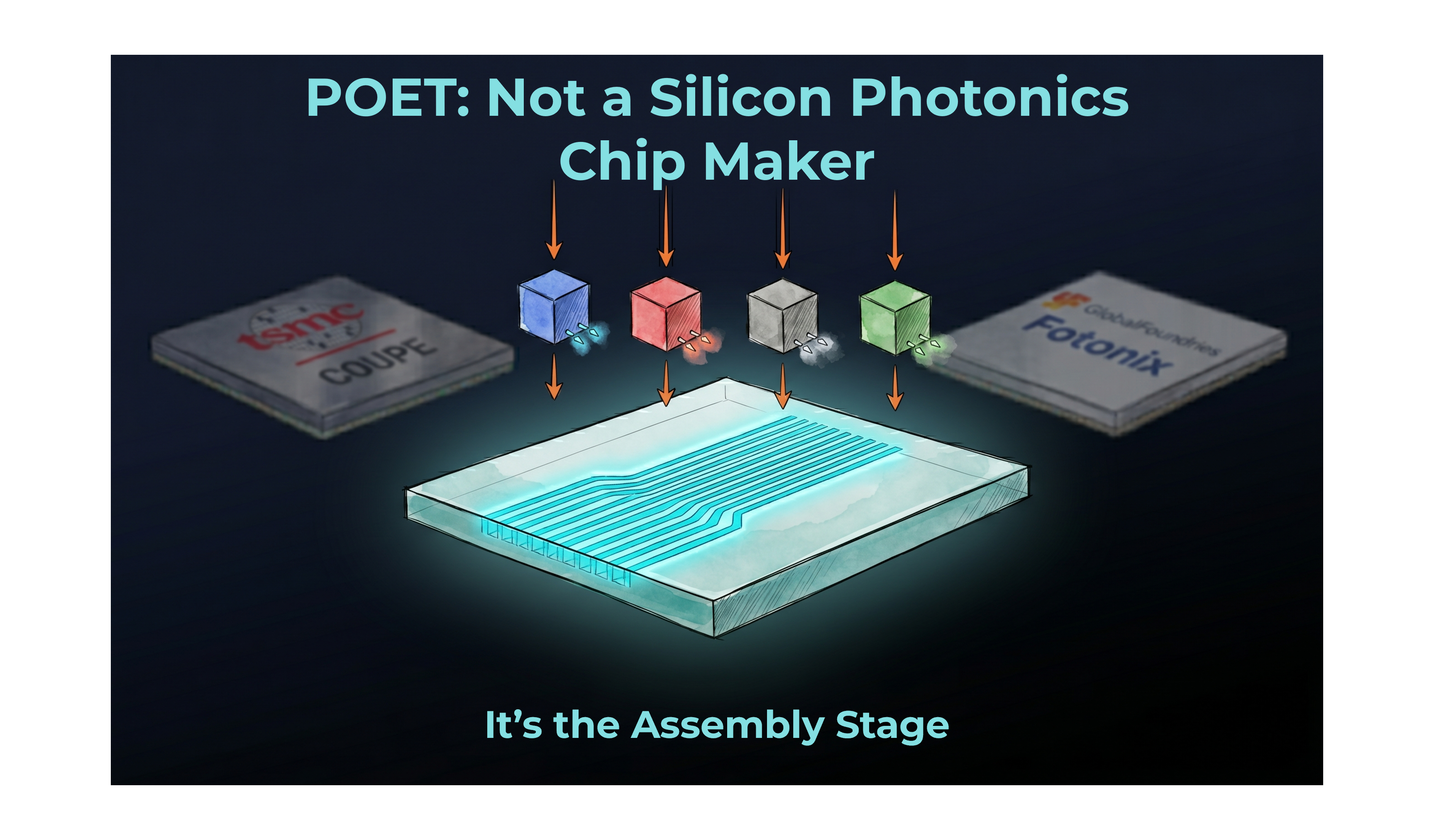
What POET holds is that stage: the optical interposer. It’s a silicon substrate with alignment structures pre-etched at the wafer level, so that laser, modulator, and photodetector chips can just be “placed” onto it and they self-align. The theoretical advantages are clear. (1) Reduced assembly cost. (2) Wafer-level scalability. (3) Versatility, because the same stage can support different chip combinations for LIDAR, 5G, or AI modules.
So why hasn’t POET broken out the way some peer optical names have? Three structural reasons.
First, revenue is nearly nonexistent. Per the audited Q4 2025 results released March 31, 2026: Q4 revenue $341,202, Q4 net loss $42.7M, cash on hand $430M [7]. TTM revenue around $1.1M. That said, the $42.7M loss breaks down very differently once you open it up. Actual operating cash out was $11.6M. The remaining $30.6M was a CAD-denominated derivative warrant fair value adjustment (non-cash, triggered by stock price appreciation), and $6.85M was from acquiring the remaining 24.8% of SPX (POET’s Singapore subsidiary). That breakdown was analyzed separately [8]. The company’s guidance of shipping 30,000+ optical engines in 2026 (announced March 31, 2026) is a forecast, not shipments already completed.
POET Technologies Q4 2025: Reading Past the Headline Loss

POET Technologies dropped its Q4 2025 results on March 31, and the market responded with a 16.93% surge to $5.94 at close. That reaction alone tells you the headline loss number wasn’t what investors were reading. On the surface, a $42.7M net loss against $341K in revenue looks brutal. But that framing misses the structure of this quarter entirely.
Second, the Wolfpack short report (April 14) aftermath. A 10-page report citing PFIC tax issues, MMCAP PIPE arbitrage, and the LFG Equities paid promotion forced U.S. retail holders to unwind before April 15. This article does not cover that. PhotonCap published a separate piece honestly addressing the Wolfpack report on technical grounds, so please refer to that [9]. The only point worth noting here is that it was one driver of short-term price pressure.
Did Wolfpack Actually Analyze POET’s Technology?

Wolfpack Research published a short report on $POET. Ten pages, 44 footnotes, zero lines of technical analysis. The PFIC tax issue and share dilution are separate matters worth examining on their own. This article reviews the report’s core claim of “seven business pivots”
Third, the dilution from the January $150M registered direct offering. 20,689,656 shares issued, closed January 23 [10]. With shares outstanding around 152.7M (as of April 17, 2026), that was roughly a 14% bump at once. The company said the proceeds would go to R&D acceleration, M&A, and operational expansion, but near-term dilution pressure is undeniable.
These three factors combined have the market hesitating. But while the market hesitates, what is the company actually building? That’s what the rest of this article is about.
Core: The $1.1B market cap POET is receiving isn’t about revenue. It’s a bet on the claim that POET sits at the most expensive step inside the optical module. Whether it actually sits there is something you verify through the equipment in the video and the academic papers, not the IR deck.
3. What the Equipment in the Video Tells You: What POET Actually Does
POET released a 12-month review video in June 2025 [11]. The title is “A Triumphant Transformation,” and if you strip out the marketing language and just look at the equipment shown in the video, you can see what POET actually does.
Three key pieces of equipment in the video are worth picking out.
Before getting into the equipment, the best conceptual framing of POET is Figure A below.
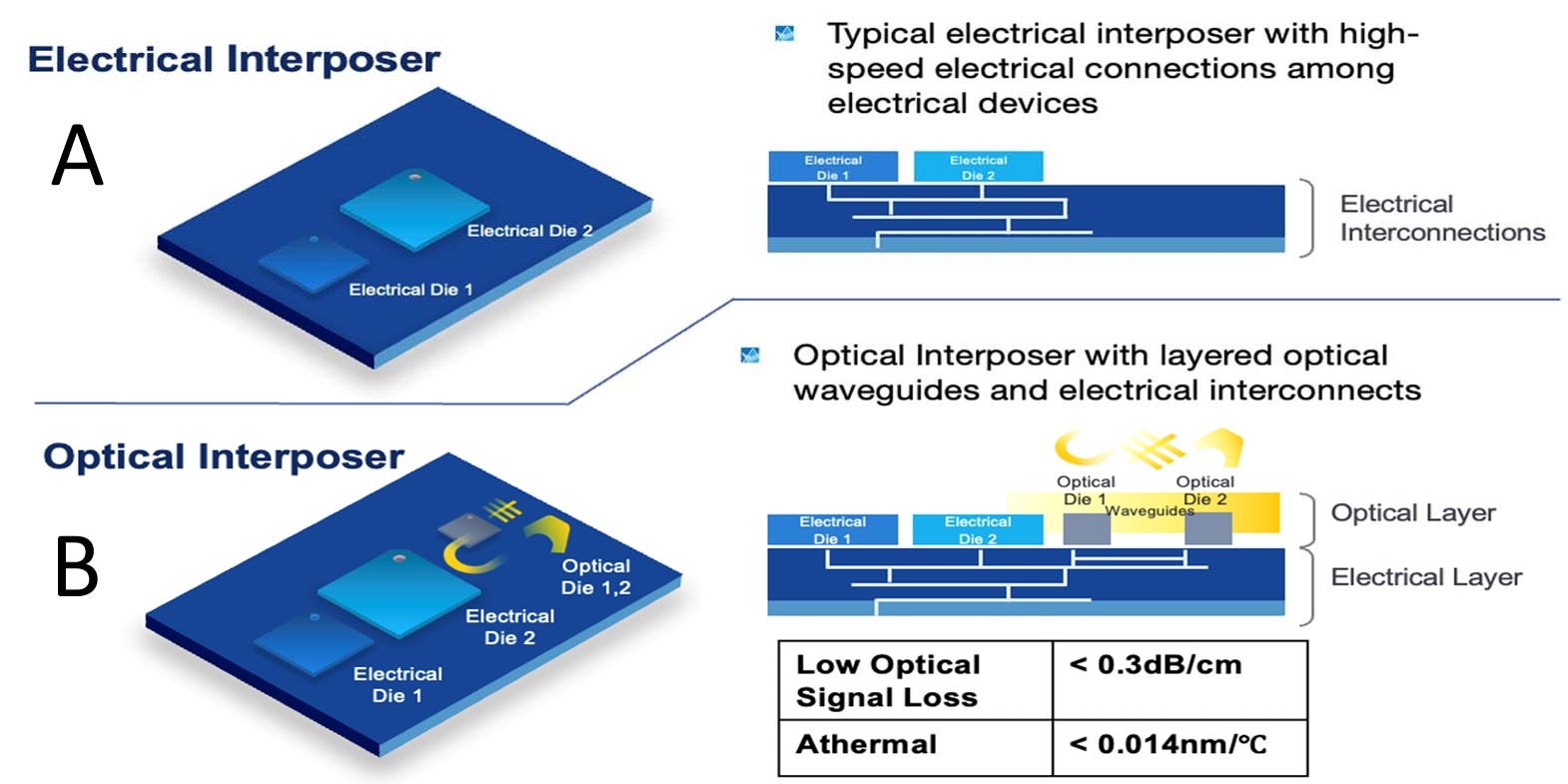
[Figure A] Electrical Interposer (top) vs POET Optical Interposer (bottom). POET’s interposer is built on top of a standard electrical interposer with additional optical waveguide layers stacked on top. Low optical signal loss <0.3 dB/cm, athermal <0.014 nm/°C. Source: Venkatesan et al., VLSI 2022 [12], Fig. 1.
So POET builds a platform where optical waveguides and alignment structures like slide-stops are pre-patterned on a standard Si interposer using CMOS processes. On top of that, EML, driver IC, and PD chips are bonded through passive assembly to produce a finished optical engine.
3.1 ASMPT AMICRA NANO Die Bonder (±0.2 μm)
In the video’s cleanroom, several ASMPT bonders are lined up. The model is AMICRA NANO. This is an ultra-precision die bonder made by ASMPT AMICRA, and its spec sheet guarantees ±0.2 μm @ 3sigma placement accuracy [13]. For optical modules, ±0.2 μm precision is best-in-class among currently available commercial equipment. Options on the same footprint include dynamic alignment system, vibration damping, in-situ eutectic bonding, three heating options (including laser soldering), and UV curing.

What having this equipment in POET’s line means: POET is not a company that bakes chips in its own fab. It’s a company that bonds known-good dies (sourced elsewhere) onto an interposer at sub-micron accuracy. More precisely, POET places III-V lasers, driver ICs, and photodetector ICs onto POET-designed interposers using ASMPT equipment in passive alignment.
The POET JLT 2023 paper explicitly references ASMPT AMICRA. “The authors are grateful to ASM-Amicra for their assistance in setting up and optimizing the bonding conditions on the Nano flip chip bonder” [14]. The equipment in the video and the equipment in the paper match.
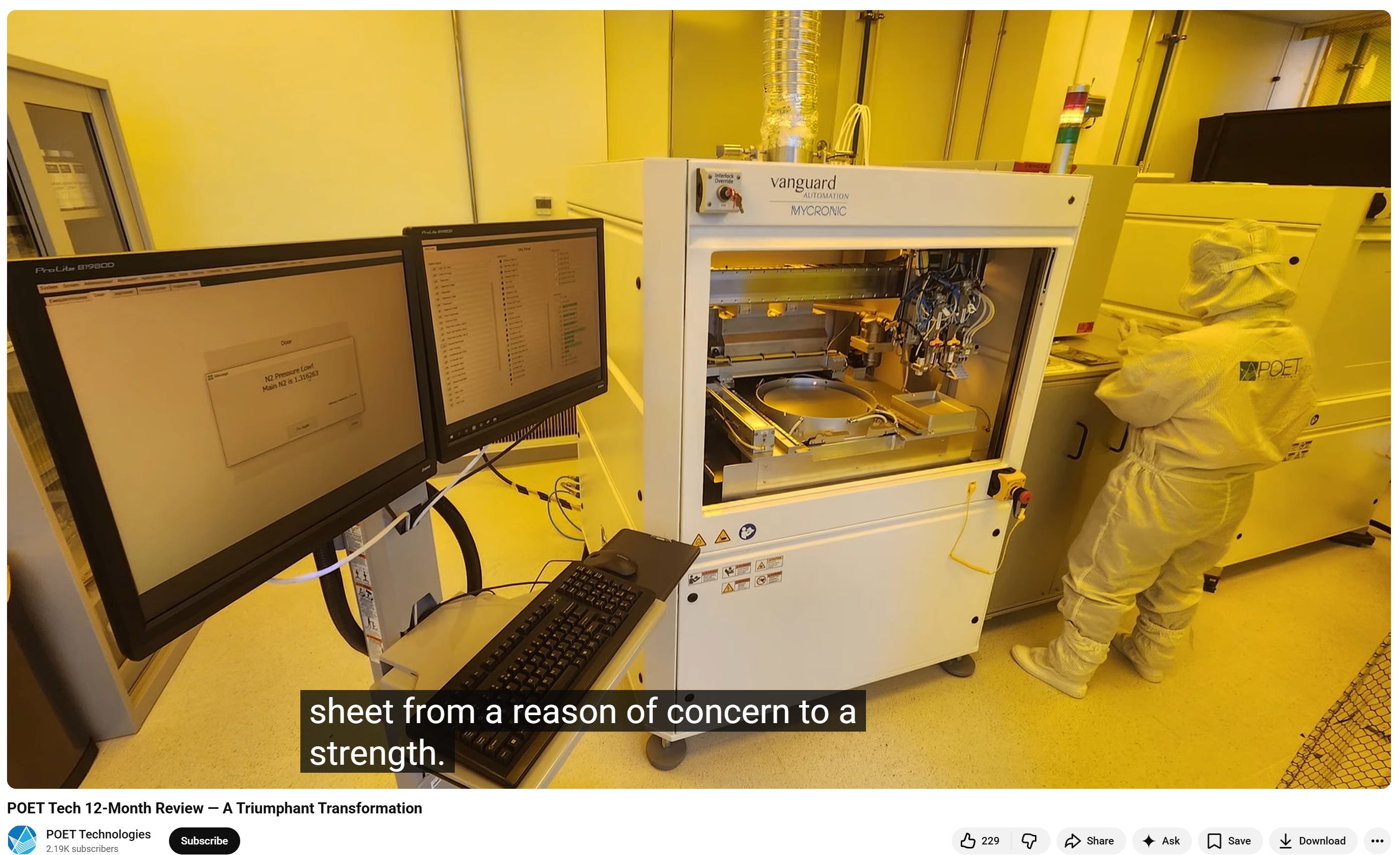
3.2 Vanguard SYMPHONY/SONATA (Mycronic subsidiary)
Another piece of equipment in the video stands out: a yellow cleanroom tool labeled “vanguard AUTOMATION MYCRONIC.” That Vanguard Automation’s lineup exists (SYMPHONY series, SONATA 1000 3D lithography, REPRISE 1000 pre/post-processing) is confirmed in Vanguard’s official materials, but which specific model the yellow tool in the video corresponds to is not officially confirmed. What is confirmed is that POET and Vanguard are officially collaborating on FaML (Facet-attached Micro-Lens) micro-lens integration. Vanguard’s parent is Sweden’s Mycronic (STO: MYCR); Mycronic acquired Vanguard in April 2024 [15].
Vanguard equipment is typically used for two applications: Photonic Wire Bonding (PWB) and Facet-Attached Micro-Lens (FaML). PWB connects two optical components through a 3D-printed free-form waveguide. FaML directly prints micro-lenses onto chip facets or fiber ends for spot size conversion or beam expansion.
POET uses Vanguard equipment for the FaML application, specifically. This is stated explicitly in the Vanguard presentation published in PIC Magazine in September 2025 [16]:
“A stand-out example is POET Technologies, which collaborates with Vanguard Automation to integrate 3D printed micro-lenses onto its optical interposers. This collaboration enhances coupling efficiency while preserving POET’s signature wafer-level passive assembly process.”
Adding FaML onto POET’s interposer gives two benefits. First, alignment tolerance relaxes to ±15 μm (per Vanguard’s own data). Compared to the ±1 μm tolerance typical of passive alignment, that’s a much larger margin, so if there’s any variation at the laser facet, coupling loss variation is reduced. Second, spot size conversion happens right at the chip facet, so there’s no need to add external micro-lenses or bulk optics. System footprint and BOM shrink.
FaML can also be used for fiber attach. Printing FaML onto the end of SMF fiber can hold insertion loss under 2 dB even with misalignment up to ±20 μm (based on Vanguard’s PWB data). Whether POET uses Vanguard equipment for this application too is not publicly disclosed, but because both applications are possible on the same SONATA 1000 equipment, the possibility is open.
To summarize: POET’s primary technology is elastic-averaging-based passive alignment, and Vanguard FaML is a complementary technology that strengthens coupling efficiency and alignment tolerance. The combination of these two is how POET maintains the “wafer-level passive assembly” identity while securing practical yield.
3.3 Wafer-Level Burn-in (SMBI)
There’s another scene in the video: a gray cabinet labeled “SMBI #1, SMBI #2,” with an operator inserting a card. POET’s caption identifies it as “wafer level burn-in equipment.”
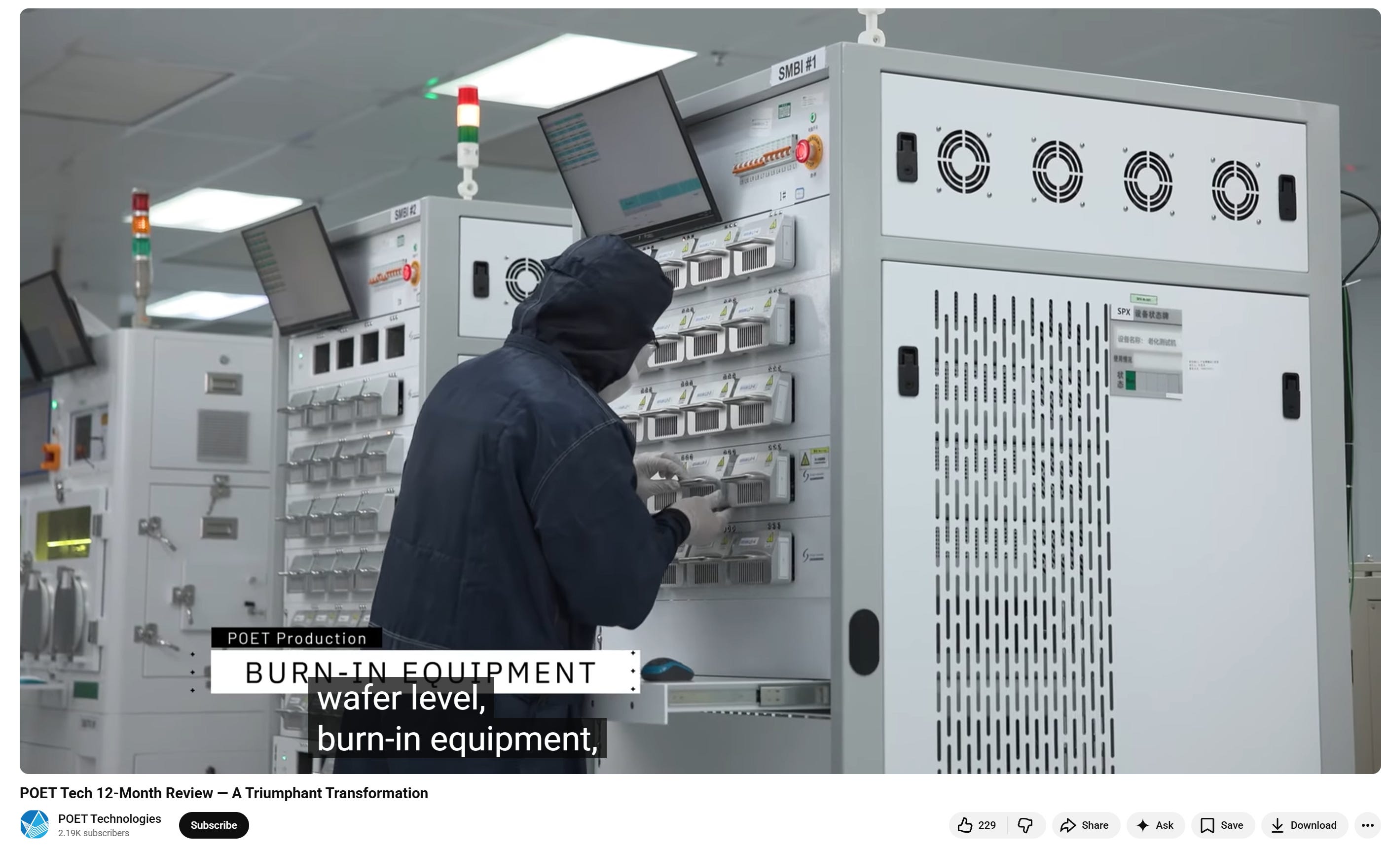
What “SMBI” stands for is not verified through any official source. Two possibilities. (1) An internal code referring to a product from Semight Instruments, a Chinese vendor (WLBI3700 and WLBI3800 series, specialized in SiC wafer + laser diode burn-in, up to 20 wafers simultaneously, temperature range -40°C to 175°C [17]). (2) POET’s internal naming. The cabinet design in the video looks similar to Semight’s product line, but 100% confirmation is difficult. It appears to be a separate tool from AEHR Test Systems’ FOX-XP (traditionally the mainstream in this market [17]).

Why this matters. In optical modules, burn-in is the core process for known-good die (KGD) selection. III-V lasers are very vulnerable to thermal degradation, and a defective chip inside a module kills the entire module. Module prices run from hundreds to thousands of dollars, and the module has to be scrapped along with the GPU it’s paired with, so losses are steep. That’s why burn-in at the wafer level, to filter out defective chips before packaging, is essential. POET having its own burn-in line means that even within the fab-light strategy, the company wants direct control over KGD selection. Even if it isn’t AEHR-class mainstream equipment, the point is that equipment capable of laser diode wafer burn-in is confirmed functional in POET’s line.
3.4 So What Kind of Company Is POET?
Putting the three pieces of equipment together, POET’s identity fits into one line.
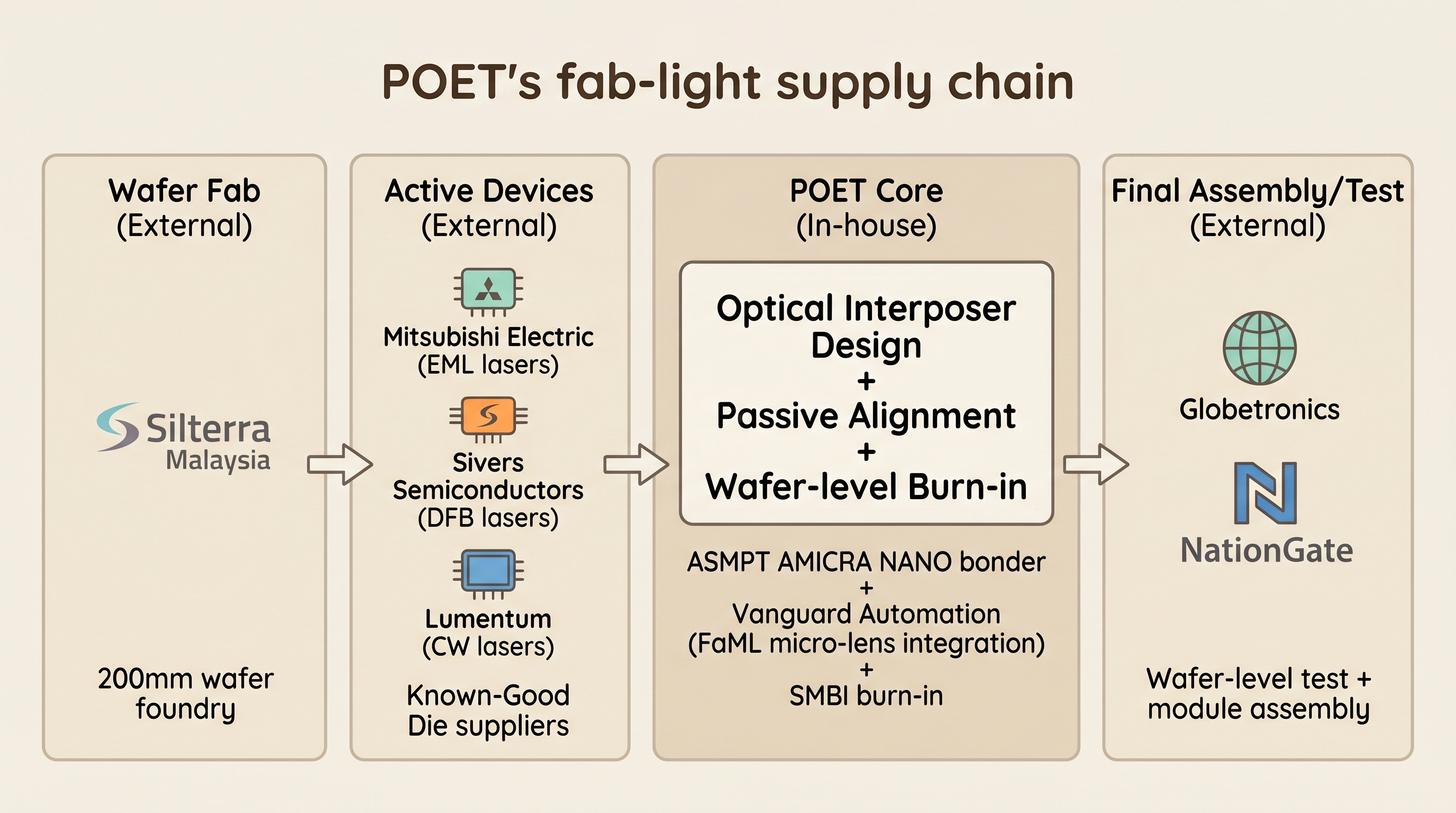
POET is a design and packaging company. The wafer fab is Silterra Malaysia (outsourced), final assembly and testing goes to Globetronics and NationGate (Malaysian outsourced manufacturing partners), active devices come from multiple suppliers including Mitsubishi Electric, Sivers Semiconductors, and Lumentum, and the core alignment / bonding work is done on ASMPT equipment in POET’s own line. That’s the substance of what POET calls its “fab-light” strategy.
The ROI logic is clear. Without spending fab CapEx (hundreds of millions to billions of dollars), POET sits at the two highest-value-add steps inside the optical module: (1) interposer design and (2) precision bonding. Chips themselves become commodities over time, but the know-how of interposer design plus precision bonding has a deep learning curve.
[Figure 1: POET’s fab-light structure diagram]
Core: POET doesn’t build its own fab. Instead, it concentrates on the two highest-value-add steps inside the optical module (interposer design + precision bonding). Equipment vendors like ASMPT and Mycronic become direct leading indicators of POET’s production ramp.
4. Elastic Averaging: How JLT 2023 Validated Sub-Micron Alignment
There’s a paper that validates the accuracy of POET’s core passive alignment technology at the academic level. Journal of Lightwave Technology (JLT), Vol. 41, No. 12 (2023), jointly published by POET and NUS (National University of Singapore): “Multi-Axial Elastic Averaging for Sub-Micron Passive Alignment of Photonic Components” [18]. JLT is published jointly by IEEE Photonics Society and Optica, with the following objective metrics per Optica Publishing Group’s official 2024 JCR summary: Impact Factor 4.8, JCR Optics category 26/125 (Q1, roughly top 20.8%), Engineering Electrical & Electronic 88/366 (Q1), Telecommunications 30/120 (Q2), #7 in Optics by Total Cites, Google Scholar h5-index 86 [19]. Per IEEE Photonics Society’s page, acceptance rate is reported below 50%. Top-tier in Optics, with rigorous peer review, so data has to pass reproducibility standards to get published.
The core idea is a precision-engineering concept called “elastic averaging.” In everyday terms: if you put a mug on a desk with one small bump under its base, the mug tilts. But if there are several bumps and a slightly compliant layer, then when pressure is applied, all bumps slightly deform at the same time and the mug settles evenly flat. Multiple contact points, each deforming a tiny amount elastically, “average out” into an accurate position automatically.
POET applies this principle to optical component alignment. Small pedestals (slide-stop pedestals) are pre-patterned on the interposer, and matching recesses are patterned on the bottom of the chip. When the chip is placed onto the interposer, the pedestals engage the recesses, and applying pressure causes small elastic deformation that locks the chip into its correct position. No camera-in-the-loop active alignment required, and sub-micron accuracy still comes out.
Here are the paper’s core results.
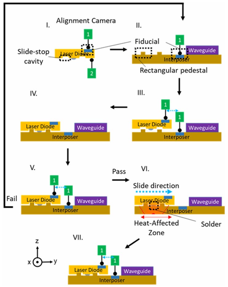
[Figure B] POET’s 7-step multi-axial elastic averaging coupling assembly process. (I) Slide-stop cavity + Alignment Camera, (II) Fiducial + Rectangular pedestal, (III) chip aligned on interposer, (IV) Placement verification, (V) Pass/Fail, (VI) Slide direction (LAB heat + Solder + HAZ, slide-and-stop), (VII) Final bonding completed. Summarizes POET’s passive alignment working principle in one figure. Source: Goh et al., JLT 2023 [18], Fig. 2.
4.1 Triangle vs Rectangle Slide-Stop
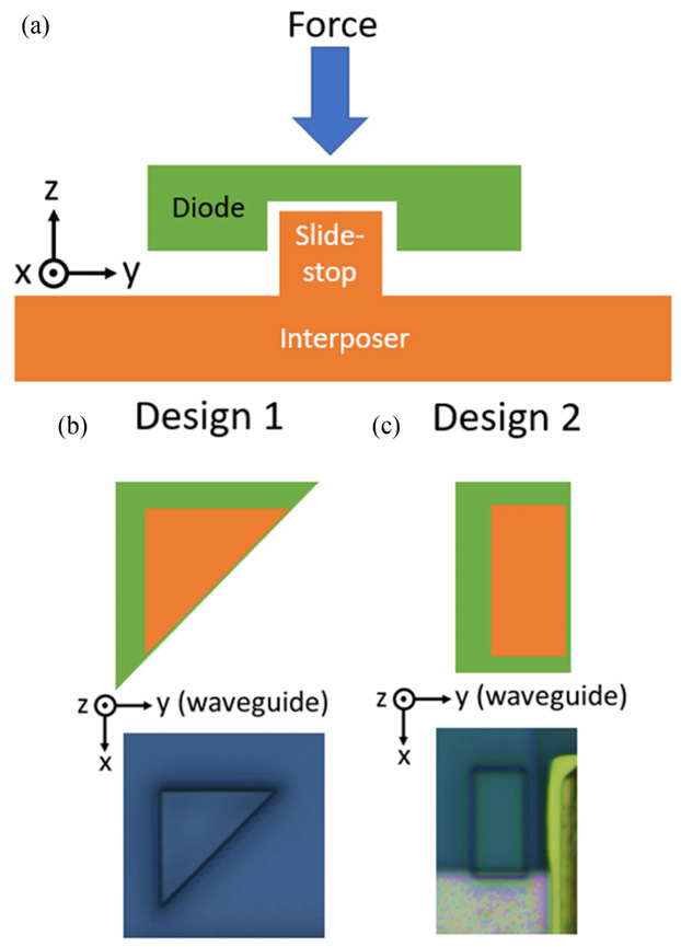
[Figure C] Slide-stop design comparison. (a) Force direction and diode / slide-stop / interposer cross-section. (b) Design 1: Triangle (internal angle 45°), strong rotation prevention. (c) Design 2: Rectangle (internal angle 90°), weaker rotation prevention. Source: Goh et al., JLT 2023 [18], Fig. 5.
POET compared two slide-stop designs: a triangle (isosceles right triangle, internal angle 45°) and a rectangle (internal angle 90°). Roughly 100 bonds each, compared statistically:
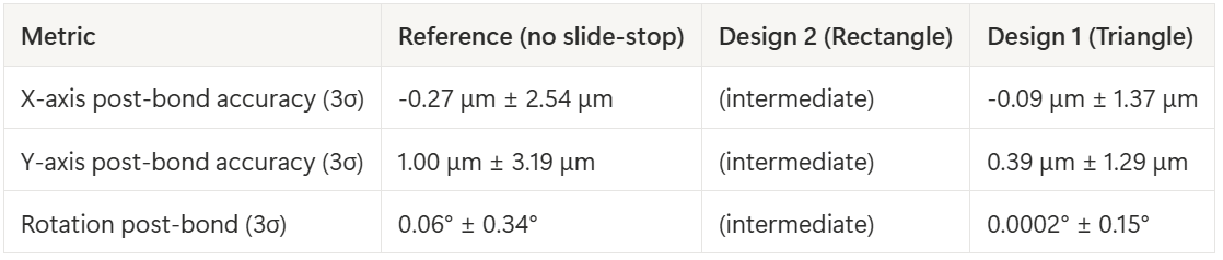
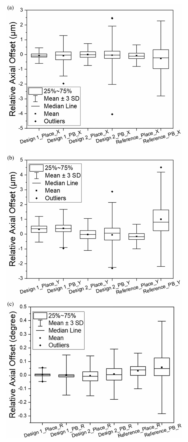
[Figure D] Placement and post-bond offset distributions for Design 1 (Triangle), Design 2 (Rectangle), and Reference (no slide-stop). (a) X-axis, (b) Y-axis, (c) θ-axis. Triangle has the tightest distribution on all three axes. Source: Goh et al., JLT 2023 [18], Fig. 7.
What the table and Figure C show is clear. Triangle design is roughly 2x better on all three axes. The reason: triangle’s 45° internal angle is smaller than the rectangle’s 90°, so during solder reflow when tiny rotation occurs, collision happens earlier and in-plane slipping is reduced.
4.2 Simulation vs Measurement Agreement
The paper also simulated laser-waveguide coupling efficiency with the FimmWave mode solver (Figure 3). FimmWave, developed by UK-based Photon Design, is a fully-vectorial waveguide mode solver with over 30 years of history in the photonics industry [20]. It includes FDM (Finite Difference Method), FEM (Finite Element Method), FMM (Film Mode Matching), and other alternative solvers, and is recognized as an industry standard for applications like Silicon Photonics, InP laser, optical fiber, and fiber-chip coupling. POET’s use of this tool means the simulation method has independent verifiability. Result: coupling efficiency held at 96% when X-axis misalignment was within 1 μm, and dropped sharply beyond 1 μm. In actual bonded Design 1 chips, the vast majority had X-offset within ±0.5 μm (Figure 8), and the output optical power distribution for Design 1 was much tighter and concentrated closer to the mean compared to Design 2 (Design 1: 6.8 mW @ Ith+40 mA, Design 2: 6.5 mW). Measurements matched what simulation predicted.
4.3 LAB’s Heat-Affected Zone (HAZ)
Another meaningful metric is LAB (laser-assisted bonding) thermal management. In the ECOC 2022 paper, POET measured LAB’s HAZ radius at 280 μm [21]. Where conventional thermocompression bonding takes 1-3 minutes, LAB completes within 10 seconds and leaves adjacent solder pads unaffected. Why this matters: when you densely package multiple components onto an optical interposer, you need to protect adjacent components from thermal damage. One reason the 1.6T module can place 4 EMLs in tight proximity is this small HAZ.
4.4 Limits of Academic Validation
What the paper showed is a lab-scale result. Statistics from roughly 100 samples. Whether a production line can make tens or hundreds of thousands consistently is a separate question. And the numbers reported are post-bond accuracy under “controlled conditions,” not validation that the process survives the full range of environmental variation in a module line (temperature, humidity, vibration, solder variation).
Still, the academic validation does mean something. JLT’s peer review passing it means at least the core passive alignment mechanism has been presented as reproducible data at the academic level. Production transition, BOM economics, and financial value are separate domains and this paper doesn’t adjudicate those.
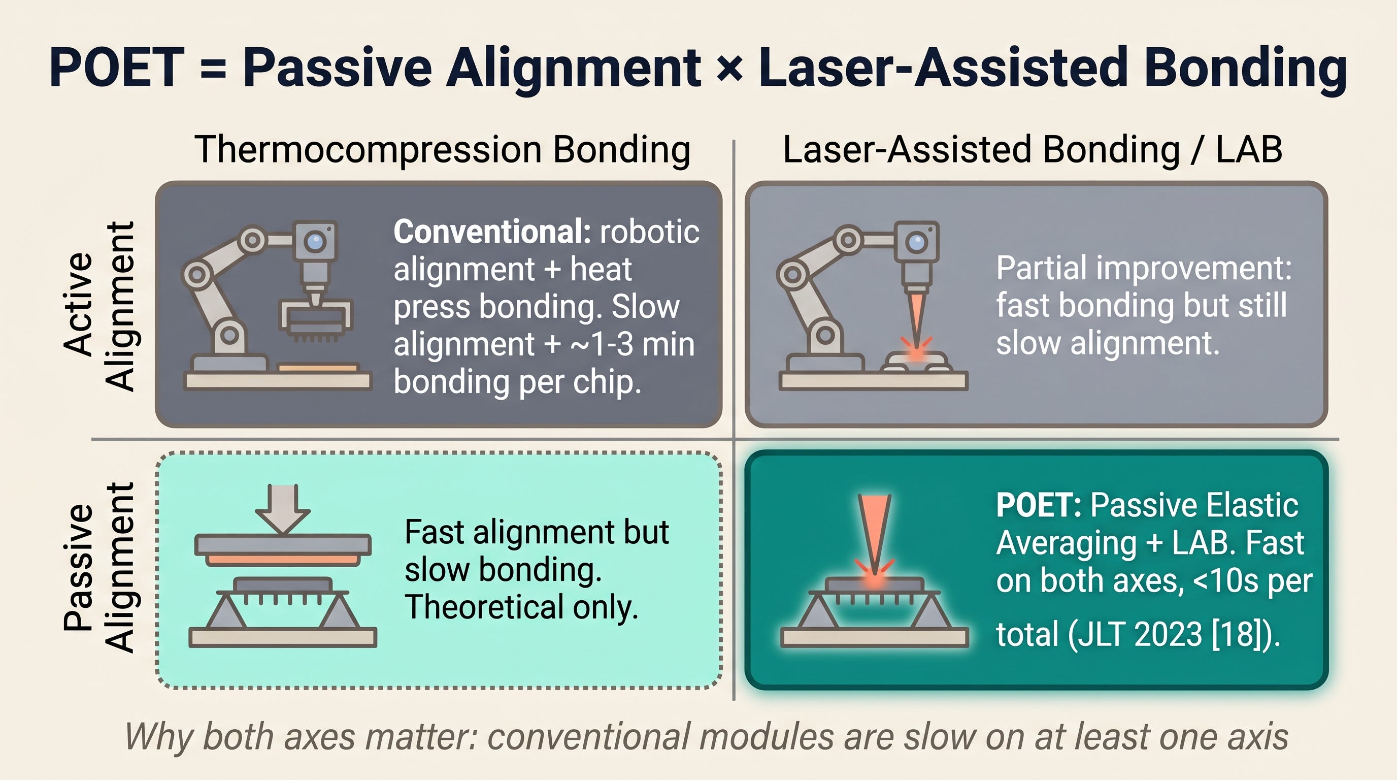
[Figure 2: POET’s two axes (Alignment × Bonding) 2x2 matrix]
Core: The JLT 2023 paper validates that POET passive alignment achieves sub-micron (post-bond X 0.09 μm, Y 0.39 μm @ 3σ) accuracy at lab-scale with reproducible data. Production transition is a separate question, but the academic legitimacy of the underlying technology has been established.
The next section covers what specs this academically validated technology produces in an actual 1.6T production product. The data POET disclosed at ECOC 2025.
5. The 1.6T 2xFR4 PIC: Measured Specs Disclosed at ECOC 2025 (paid)
POET presented a paper at ECOC (European Conference on Optical Communications) in September 2025: “Hybrid Integrated 1.6T 2xFR4 Transmitter PIC using a CMOS based Optical InterposerTM” [22]. This is the first measured data point for gauging POET’s actual competitiveness in the 1.6T optical engine market.
5.1 Making 1.6T with 4 Lasers
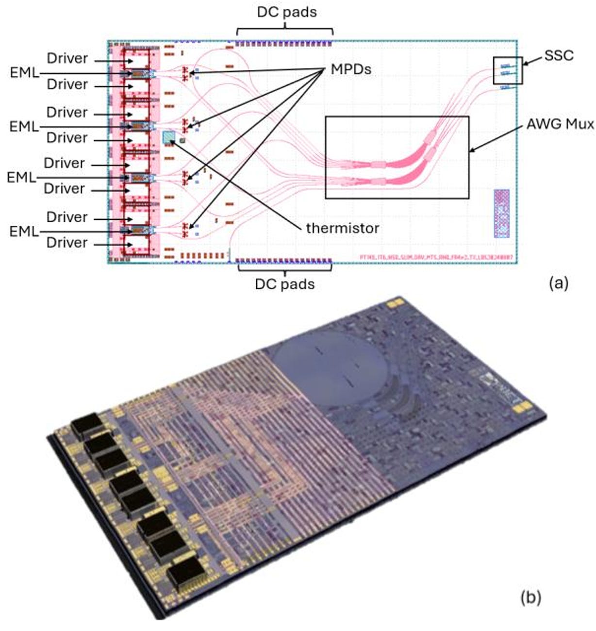
[Figure E] 1.6T 2xFR4 transmitter PIC. (a) Layout: 4 EMLs + 8 drivers + AWG Mux + MPDs + SSC + thermistor placed on a SiN interposer. (b) Actual post-bond chip photo, dimensions 14.32 mm × 7.975 mm. Source: Mo & Venkatesan, ECOC 2025 [22], Fig. 1.
Conventional EML-based 1.6T modules need 8 lasers (200G/lane × 8 lanes). POET uses only 4. How? The key is a special EML chip design supplied by Mitsubishi Electric.
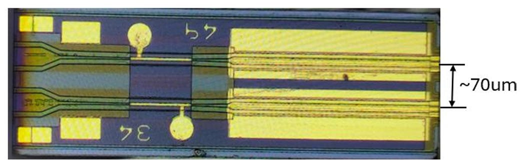
[Figure F] 400G EML chip. A single chip monolithically integrates two DFB+EAM pairs with two output facets, each facet delivering 200G, facet pitch ~70 μm. This narrow pitch can’t be coupled with a conventional micro-lens array; POET’s interposer waveguide pitch-matching is essential. Source: Mo & Venkatesan, ECOC 2025 [22], Fig. 2.
Inside this EML chip, there are 2 DFB lasers and 2 EAMs (electro-absorption modulators), with 2 output facets. The pitch between the two facets is roughly 70 μm. Narrower than a human hair.
Coupling these 70 μm dual outputs into optical fibers with external optics is essentially impossible. It’s tighter than the standard pitch of micro-lens arrays. But POET’s interposer has waveguides pre-etched at exactly that 70 μm pitch. The moment the chip is placed, both facets auto-align to both waveguides. That’s the core trick of building 1.6T with 4 EMLs.
Additionally, POET’s interposer handles the RF connection between EAM and driver IC through an internal RF layer. Direct trace, no wire bonding. Eliminating wire bonding, combined with the interposer’s RF layer, limited RF penalty and adjacent-channel crosstalk in the paper’s measurement setup (the paper doesn’t claim full elimination at industrial volume; this is worth noting explicitly).
5.2 Measured Specs
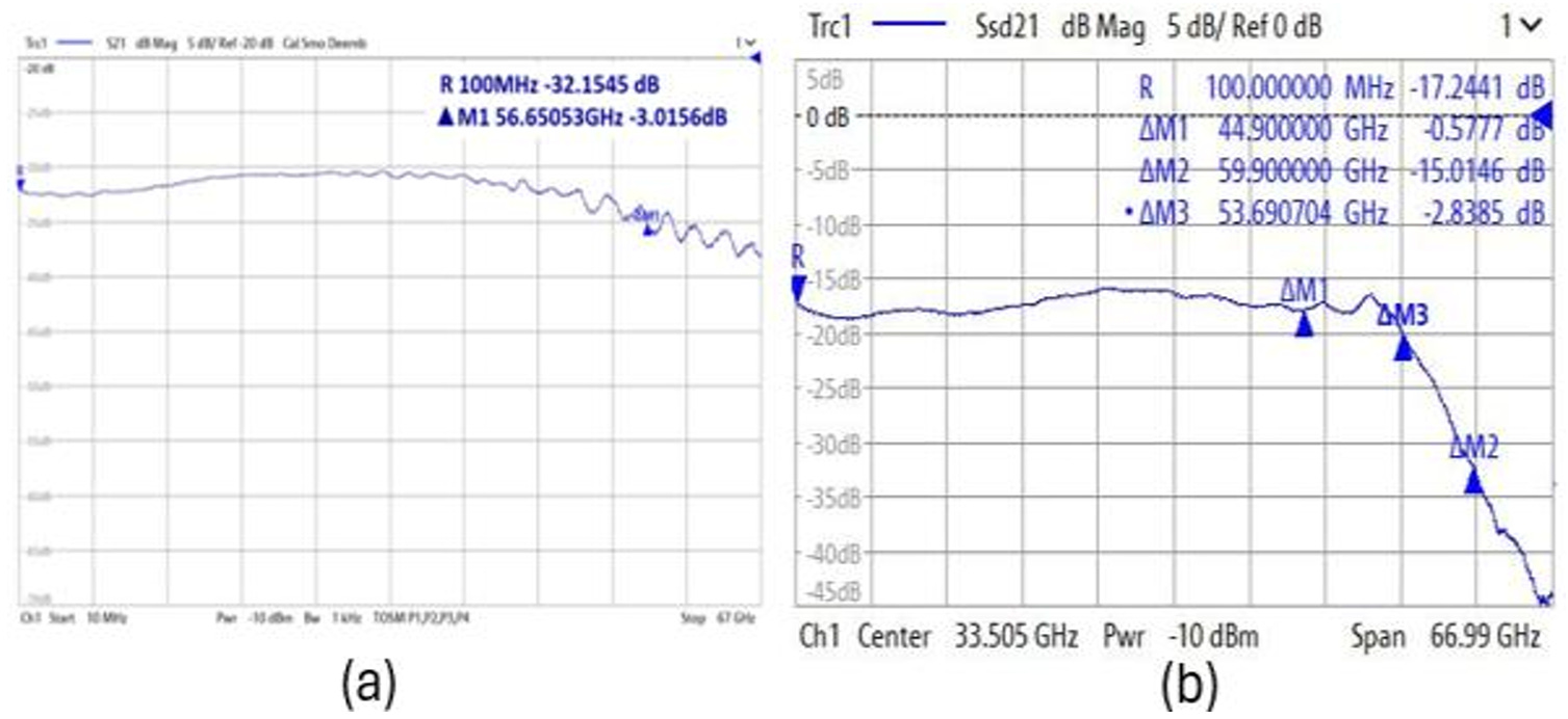
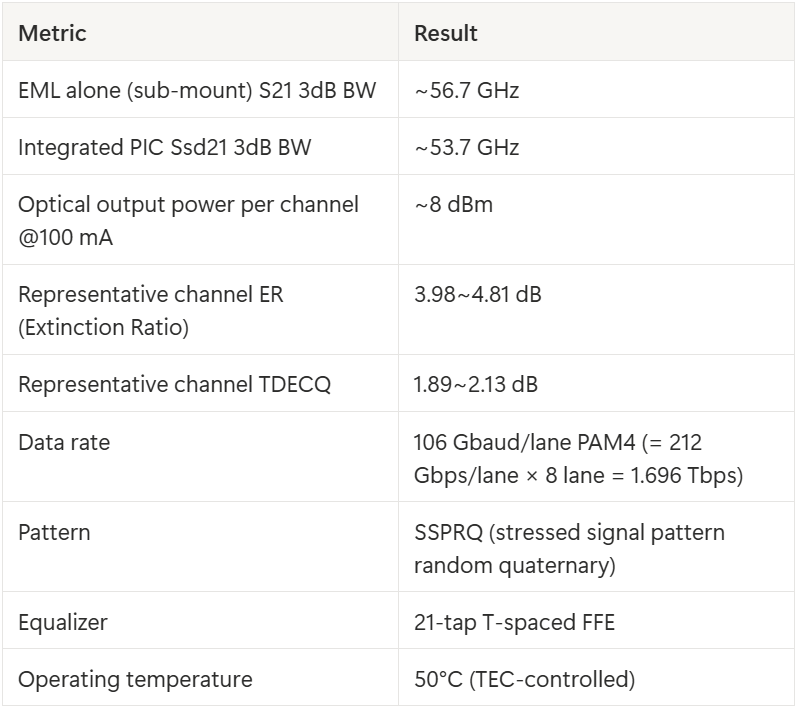
[Figure G] (a) S21 of EMLs on sub-mount ~56.7 GHz @ -3 dB. (b) Ssd21 of integrated transmitter PIC ~53.7 GHz @ -3 dB. Only a 3 GHz bandwidth loss between EML on sub-mount and fully integrated PIC assembly. Source: Mo & Venkatesan, ECOC 2025 [22], Fig. 3.
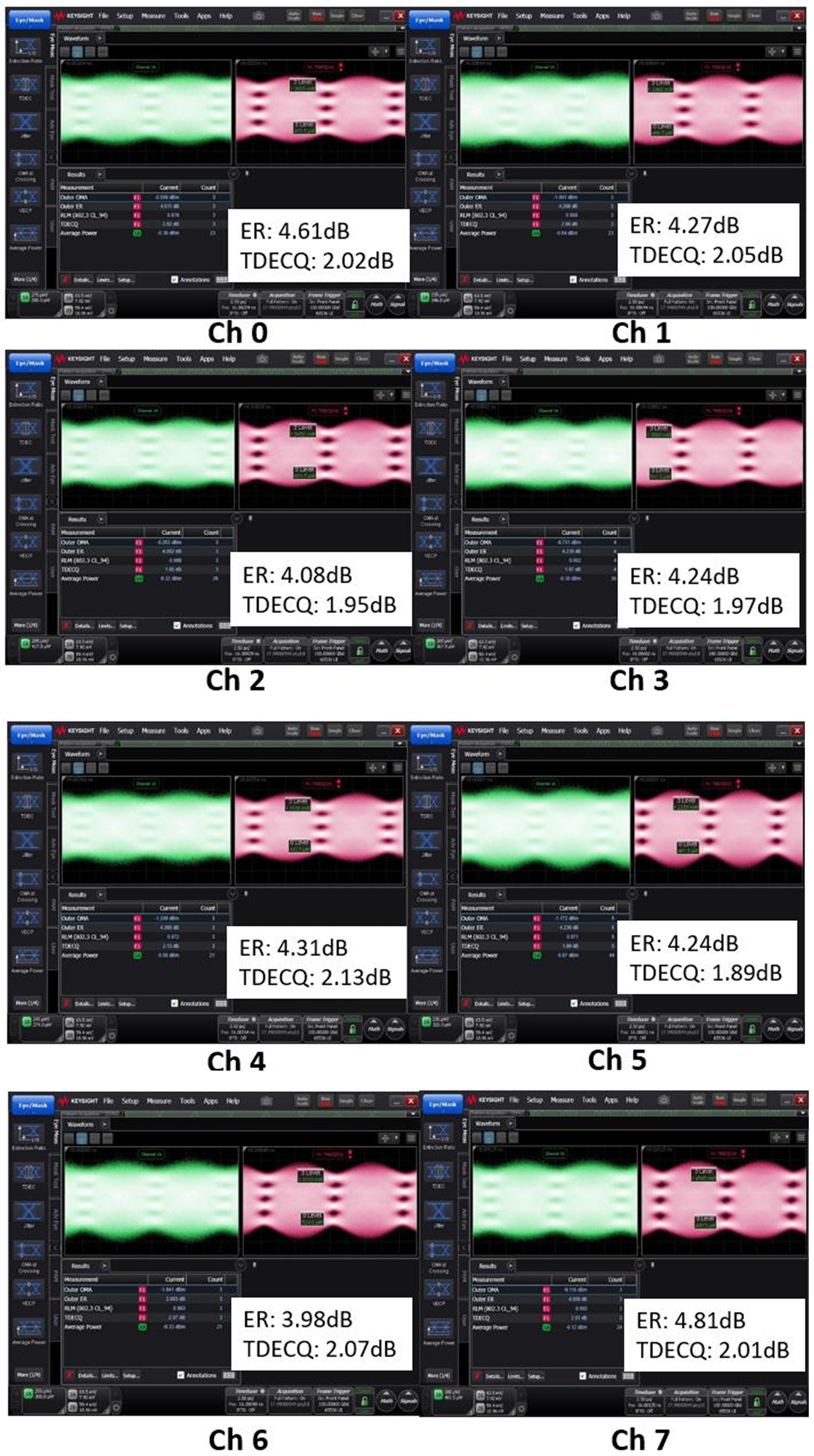
[Figure H] 1.6T 2xFR4 PIC’s 8-channel optical eye diagrams @ 106 Gbaud PAM4 (SSPRQ). ER / TDECQ per channel: Ch0 4.61/2.02, Ch1 4.27/2.05, Ch2 4.08/1.95, Ch3 4.24/1.97, Ch4 4.31/2.13, Ch5 4.24/1.89, Ch6 3.98/2.07, Ch7 4.81/2.01 (dB). All channels deliver ER >4 dB, TDECQ ~2 dB, well within the 2xFR4 transmission link budget. Source: Mo & Venkatesan, ECOC 2025 [22], Fig. 5.
Measurement results from the paper:
53.7 GHz Ssd21, compared against EML alone at 56.7 GHz, is a 3 GHz drop. That’s meaningful. Typically post-packaging RF penalty runs 5-10 GHz, but POET reduced this penalty to 3 GHz by replacing wire bonding with the interposer RF layer. In other words, POET interposer’s RF integrity has been validated at the measurement level.
8 dBm per channel is well above the 2xFR4 standard’s -3.5 dBm minimum launch power. ER 4 dB and TDECQ 2 dB meet IEEE 802.3 spec even under the SSPRQ pattern (the hardest stress signal).
5.3 Chip Size and What It Means
This 1.6T PIC is 14.32 mm × 7.975 mm. Fits into the QSFP-DD 1.6T form factor, and POET claims the same board design can support an OSFP 3.2T transceiver (integrating two 1.6T PICs).
As a comparison point, EML-based 1.6T modules built by Coherent and Lumentum don’t use dual-output EMLs. They use 8 single-output EMLs, bundle 4 wavelengths through an external 4-channel mux, then couple to optical fiber through external optics. Component count, alignment steps, and manufacturing cost are all higher than POET’s approach. POET’s key market differentiation sits exactly in this BOM and process simplification.
5.4 Limits of the Measured Data
The ECOC paper’s limits also deserve mention.
First, what was reported is “sample” level data. All 8 channels were measured at the same time, but consistency in a production line (same performance across units) is not validated. Typically lab-scale to production transition causes BER (bit error rate) tail degradation and channel-to-channel variation increase.
Second, RIN (Relative Intensity Noise) data is missing. When 4 EMLs are placed tightly on the same interposer, the degree to which thermal crosstalk between adjacent EMLs increases RIN has direct impact on the link margin of the production module. This is the key undisclosed area covered in §6.
Third, the reported measurement is at 50°C TEC-controlled. Power consumption and BER stability across the actual data center ambient range (0-70°C), with increased TEC load, are outside the paper’s scope.
That’s the end of the free section. Up to here, everything can be verified through papers and equipment photos. But the real money question comes next. What are the yield numbers? What’s the RIN? What’s the post-bond EML noise? How far along is the monolithic camp’s medium-term threat? Can POET actually pass hyperscaler qualification? The following sections answer these.
